Review: Testdriving LibrePCB Shows That It’s Growing Up Fast
There are a host of PCB CAD tools at the disposal of the electronic designer from entry-level to multi-thousand-dollar workstation software. It’s a field in which most of the players are commercial, and for the open-source devotee there have traditionally been only two choices. Both KiCad and gEDA are venerable packages with legions of devoted fans, but it is fair to say that they both present a steep learning curve for newcomers. There is however another contender in the world of open-source PCB CAD, in the form of the up-and-coming LibrePCB.
This GPL-licensed package has only been in development for a few years. LibrePCB brought out its first official release a little over a year ago, and now stands at version 0.1.3 with builds for GNU/Linux, Windows, MacOS, and FreeBSD. It’s time to download it and run it through its paces, to see whether it’s ready to serve its purpose.
Getting To Know LibrePCB
It’s refreshing to see for a project still early in its gestation, that the LibrePCB team have made an effort to provide a seamless installer rather than relying on a git command or a compressed archive. Installation on the Ubuntu system here was intuitive and easy, with selecting directories a straightforward process. When starting a test project, you’re required to set up libraries before it’s straight into the schematic editor, with as expected an easy flip between that and the layout editor.
The first impression of the interface is that it’s much simpler and more intuitive than its open-source competitors, as a former Eagle user who’s never found herself completely at ease with KiCAD I immediately felt at home. That learning curve I mentioned was largely absent, and though not everything is in quite the same place, the workflow and methods are similar enough to get started without any problems.
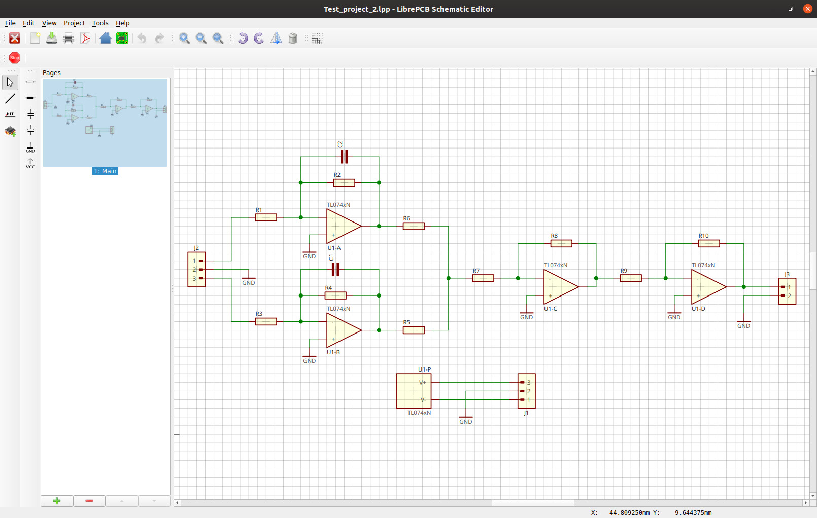
Without anything in particular to build, I set straight in to a simple multivibrator to put it through its paces, and then for something a little more complex an analogue mixer with a ground plane. Immediately a shortcoming of such a youthful piece of software fell into sharp relief, as it became obvious that the component libraries shipped with it were far from comprehensive and in many cases symbols lacked footprints. Not a problem, indeed it gave a convenient chance to take a look at the footprint and symbol editors to create a new component.
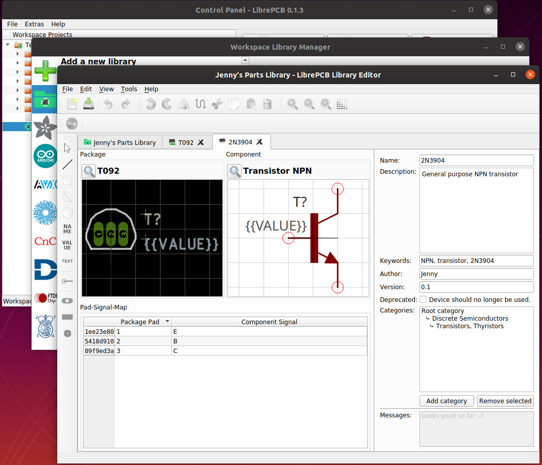
Call me old-fashioned, but my first simple test was a discrete 2N3904 transistor. It was a simple enough footprint to create but I found I couldn’t create the desired TO-92 circular outline due to the lack of ability to create an arc. I had to make do with a join-the-dots line, but I’ll take it. Maybe I should have arranged the pads in a triangle rather than a line, but LibrePCB lets you add alternative footprint easily enough. Instead of treating a package as a single footprint it can hold a variety of different footprints and types of the same component in a single one of its packages, so for instance for my TO-92 package could contain in-line, triangle, and ammopack versions.
A Few Rough Edges Still To Be Found
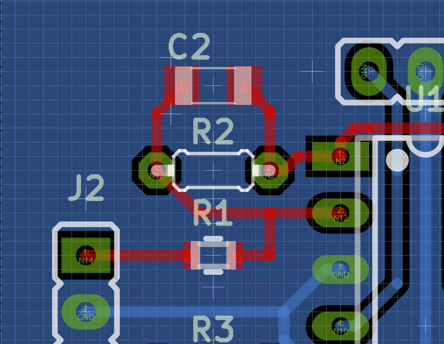
An unexpected issue showed itself as I created my component layout. I had selected one of LibrePCB’s stock SMD resistors in my schematic, but what showed up in the board was a through-hole component. Checking the stock component’s package in the component library revealed nothing but the SMD footprint in the component I had selected, but there it was. Creating a new SMD resistor component and substituting it for the stock model brought the correct footprint onto the board, but evidently I had stumbled upon one of the rough edges inherent to what is still an alpha piece of software.
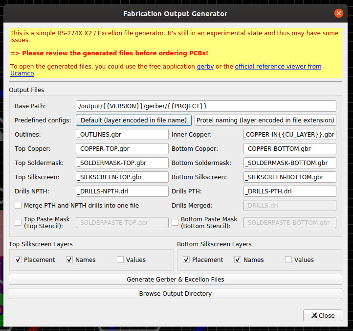
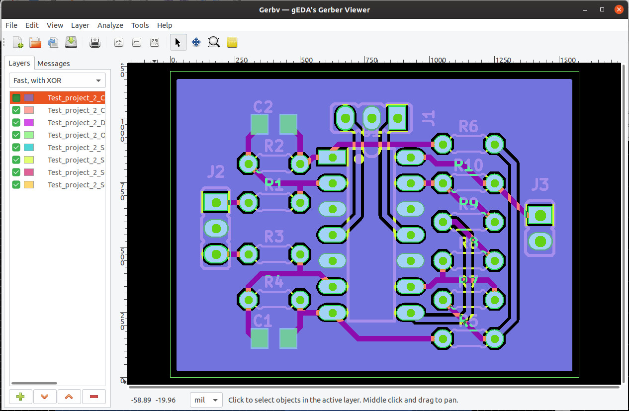
The point of a PCB CAD package though is to make PCBs, so next up was to run a design rule check and export my design. Writing this just as Chinese New Year is upon us there’s little point in ordering PCBs for a couple of projects I don’t want anyway, but I can still create a set of Gerbers and take a look at them in gerbv.
Design rule checking is a new feature in version 0.1.3 and an annoyance is that it doesn’t save any changes you make to the defaults, but it does warn you of this and lead you to expect that this will change. It would be nice to have the option to load and save different DRC settings to hold the various demands of different board houses. Gerber export is extremely straightforward though, and I soon had a set of files that loaded up with a board that appeared exactly as I expected in gerbv. I have no reason to believe that if I sent them to a board house I wouldn’t shortly receive a set of PCBs without queries about the quality of what I had sent.
Is It Ready For The Big Time?
It’s quite possible then to use LibrePCB as it stands to design a simple PCB and create the Gerbers for a board house. You can certainly give that a go, but while they’ve made a commendable achievement of a remarkably usable piece of software for one at such an early-stage in its life it’s still one that has a little way to go. There will be a few bugs, it’s evident that there are features still to be implemented in future versions, and the stock libraries are hardly comprehensive. Both of the first two will inevitably improve with subsequent releases, and the last will grow as the user base expands.
Whenever a new open-source project arrives that does the same task as an established software libre player there are inevitably voices that decry it, as though somehow it is diluting the available resources for its competitor. I don’t agree with this view as I see diversity as essential to the ecosystem, but it’s worth asking what LibrePCB will achieve and where it will find a niche.
Perhaps the answer to that question will satisfy those worried it might take resources from the likes of KiCAD then, because after using it I feel its strengths lie in a completely different direction. A few years ago the default in our circles was Eagle, but the sale of that package to Autodesk and subsequent move to a subscription model has weakened that hold. LibrePCB is unlikely to tempt the professional Altium user or the established KiCAD user, but its ease of user interface migration for long-time Eagle users gives it an opening that KiCAD struggles with. If they can enhance that experience and provide a migration path for Eagle projects in both old and new formats I think they’ll be on to a winner, and could easily become a regular sight in projects we feature here.
So, should you install LibrePCB? By all means, install it, get to know it, and contribute to it if you have the relevant skills. Should you use it to design PCBs? You certainly can and there’s no harm in trying, but you’ll inevitably run into one of the limitations in the current version due to its early-stage status. Should you abandon your other tools and make the move to the current version of LibrePCB for all your work? Probably not, unless you like to live dangerously. I think LibrePCB is one to watch, they’ve done a very good job so far and I think there is a possibility for an extremely useful piece of software from it in the future. Watch that space.
from Hackaday https://ift.tt/2RE8w8F
via IFTTT